

GATES BELTS, HOSES, AND APPLICATIONS
Thursday, December 17, 2015
Friday, December 11, 2015
Hydraulic Fluids
Hydraulic fluids can be categorized as petroleum-based, water glycol or synthetic based (i.e.,
phosphate ester). All types provide
specific properties that need to be considered to meet the needs of a given hydraulic
application.
In the
past, hydraulic fluids were petroleum based fluids that could potentially cause problems by leaking into
the ground and contaminating the area and water supply. Today, the industry is
moving toward more environmentally friendly fluids where advances have led to
many new generations of “green” fluids.
Green
fluids are typically synthetic- or vegetable-based. Green fluid’s base compound may be biodegradable and non-toxic, however, additives in the fluid may not be.
Synthetic fluids are primarily ester-based.
Vegetable oils are gaining popularity since they cost
less than synthetic and are more biodegradable. They also have excellent
lubricity and a high viscosity index. However, they have a limited temperature
range with rapid oxidation at elevated temperatures.

Tuesday, December 8, 2015
Poly Chain GT2 Sprocket Specifications
Poly Chain GT2 sprockets are manufactured to close tolerances to ensure proper drive alignment, tooth engagement, and overall drive performance. Modifications such as reboring may result in unsatisfactory results in the belt drive system. Strict adherence to the standard tolerances outlined below is highly recommended.


For any additional questions feel free to look through our other blog topics or contact us at ptpasupport@gates.com or 303-744-5800.
Wednesday, December 2, 2015
Calculating Sprocket Pitch Diameter
When working with synchronous sprockets you'll need to know about pitch diameter.
In the image below you can see that the pitch diameter on a sprocket is an invisible dimension that represents where the pitch line of the belt would be if it was wrapped around the sprocket. Calculating pitch diameter is simple.
Pitch Diameter = (Belt/Sprocket Pitch) * (# of sprocket grooves) / π

More - Maximizing Hose Assembly Service Life
Maximum service
life can be attained by following with the
recommendations shown below.Hose Routing–Restraints, protect or guide hose (clamps) can be used to minimize risk of damage due to excessive flexing, whipping or contacting other moving parts or corrosives. Determine hose lengths and configurations that will result in proper routing and protection from abrasion, snagging or kinking and provide leak resistant connections.
Hose Length–Correct
hose length determinations include considerations for length changes under
pressure, machine vibration and motion, and hose assembly routing.
Hose Applications–Select
the proper hose for the application.
Vacuum service (for example,
Gates Global MegaVac®), special fluids or high temperature capabilities are
among the applications requiring particular consideration and a specific hose.
Do not use Gates hydraulic hose in place of permanent piping. When additional information
is required, contact Product Application Engineering.
Maximizing Hose Assembly Service Life
Maximum hose assembly service
life can be attained by following the recommendations shown below.
Fluid Compatibility–The
complete hydraulic assembly (tube, cover, reinforcement and couplings) must be fluid
compatible. Phosphate ester and petroleum-based hydraulic fluids have
drastically different chemical characteristics therefore it is important that the correct hose must
be used. Hoses are compatible with many, but not all fluids.
Gates G2XH and C5D hoses are unique because they are capable of handling both phosphate ester and petroleum-based
hydraulic fluids.
Minimum Bend Radius–Do
not bend or flex hose to a Bend Radius smaller than the recommended minimum Bend Radius
or subject the hose to tension or torque. These can place excessive stress on
the reinforcement and severely reduce the ability of the hose to withstand pressure.
Hose
Size–The hose size (inside diameter) must be adequate
to keep pressure loss to a minimum or required flow volume. Inside diameter
that is too small for a given volume of flow results in excessive fluid turbulence,
pressure drop, heat generation and tube damage. It is generally a best practice
not to exceed16 feet per second fluid velocity in a hydraulic system. Using a
larger I.D. hose will lower fluid velocity.
Maximizing Hydraulic Hose Assembly Life
Maximum service
life can be attained by complying with the
following
recommendations:
Working Pressure–The
hydraulic system pressure should not exceed the rated working pressure of the hose.
Pressure surges or peaks exceeding the rated working pressure are destructive
and must be taken into account when selecting a hose. It is not safe to use
hose assemblies above their rated working pressure.
Minimum Burst Pressure–Burst
pressures are reference pressures intended for destructive testing purposes and
design safety factors only. Do not subject hose to the Minimum Burst Pressure.
Temperature Range– The
hose should not be exposed to internal or external temperatures that exceed the
recommended limits.
Consult Product Application when hydraulic fluids contain emulsions or solutions. Some
fluids reduce the safe operating temperature of a hose therefore the fluid manufacturer’s
recommended maximum operating temperature for any given fluid must not be exceeded,
(i.e. water in a hydraulic hose).
Hose Assembly Performance
Hydraulic hose
and hose assemblies have a performance life which is dependent on
service conditions of the application
·
Subjecting hose (and hose assemblies) to
conditions more severe than the recommended product limits can reduce service life
·
Subjecting hose to combinations of circumstances at or near recommended rating limits (i.e., continuous use at maximum rated
working pressure while at maximum recommended operating temperature or minimum bend
radius)
Injury to
personnel and/or damage to equipment could be the result by not following proper
selection, installation and maintenance procedures.
Hose assemblies in
service should be regularly inspected for leaks, abrasion, kinks, cover
blisters or other such damage. Assemblies showing signs of wear or damage should
be replaced immediately.
Tuesday, November 17, 2015
Useful Formulas and Calculations
Here is another page out of the back of our Drive Design Manuals. This page out of the Useful Formulas and Calculations section has some great conversion information for you. Here is a link to our Poly Chain GT Carbon Drive Design Manual in case you'd like to see more.

Friday, November 13, 2015
Stainless Steel Poly Chain® GT2® Sprockets and Bushings
Gates carries limited lines of stainless steel Poly Chain
GT2® sprockets and Taper Lock™ bushings. 8mm pitch Poly Chain GT2 sprockets are
available in 12mm and 21mm widths with groove counts ranging from 28 to
60. Corresponding stainless steel Taper
Lock bushings are available in sizes ranging from 1108 to 2012 in both English and
metric bore sizes.

Specific types of stainless steel materials used in
sprockets and bushings can vary depending on cost and availability. Typical stainless steel material types 301, 302, 303 and 304.
Stainless steel sprockets and bushings provide a corrosion
resistant combination that performs very well in applications that are wet or
sustain regular wash downs. Standard
sprocket and bushing materials are not appropriate for use in these adverse environments.
And Poly Chain GT Carbon belts are highly resistant to
moisture and most wash down chemicals.
Conventional rubber synchronous belts can absorb moisture and swell, as
well as lose significant tensile strength in continuously wet environments.
For further information contact Gates Product Application
Engineering at 303.744.5800 or ptpasupport@gates.com.
Friday, November 6, 2015
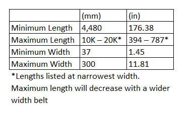
14MGT Poly Chain® GT® Carbon™ Extended Length™ Belts
Gates has a new 14 mm pitch Poly Chain manufacturing process which allows for new and longer belt lengths. With this process, Gates can make any tooth count within the minimum and maximum length range. Most importantly, both the tensile properties and load capacity of the Extended Length belts match traditional endless belts.

The new Poly Chain Extended Length belts are currently available per the following guidelines:
Contact Gates Product Application Engineering at ptpasupport@gates.com or +1.303.744.5800 if you have any questions regarding application of this new product.

The new Poly Chain Extended Length belts are currently available per the following guidelines:

Contact Gates Product Application Engineering at ptpasupport@gates.com or +1.303.744.5800 if you have any questions regarding application of this new product.
Tuesday, October 27, 2015
What's the Difference Between GT, GT2, and GT3?
Gates currently offers Poly Chain GT Carbon belts that are designed to run in Poly Chain GT2 sprockets. There are also PowerGrip GT3 belts designed for PowerGrip GT2 sprockets. What's with the GT, GT2, and GT3?
It's easy to get caught up in the product line names, but don't let it throw you off. "GT" stands for "Gates Tooth" which describes the belt's patented curvilinear tooth profile. The reason there are GT, GT2, and GT3 products is because there have been changes in the construction of the belts and sprockets over the years. For example, Gates is now selling the third generation of PowerGrip belts with the GT tooth profile. That product line's corresponding sprockets are on their second generation. That's why PowerGrip GT3 belts are used in PowerGrip GT2 sprockets.
This applies to Poly Chain components as well. Poly Chain GT and Poly Chain GT2 belts had aramid tensile cords. The current third generation of Poly Chain belts use carbon tensile cords, hence the product line name "Poly Chain GT Carbon". The sprockets are currently on their second generation which is why Poly Chain GT Carbon belts are used in Poly Chain GT2 sprockets.
Poly Chain GT Carbon Length Tolerance
We occasionally receive inquiries regarding the length tolerance for our Poly Chain GT Carbon belting. This can arise out of simple curiosity or when a customer is concerned with designing a fixed center drive and wants to ensure they account for any length tolerance. It is important to note that the actual tolerance for belt length comes by way of a center distance tolerance. This center distance tolerance is used as a more functional value given the belt length is a pitch length which is nearly impossible to measure directly. The most functional way to measure the belt length is to use specially machined measuring sprockets with the belt installed and then determine the center distance and compare it to the nominal value. Given this, below is chart from our Poly Chain GT Carbon Drive Design Manual which outlines the center distance tolerance per belt length range.
It is important to note that these values would need to be compared using specially machined measuring sprockets and should not be referenced when using standard, off the shelf sprockets as these table values do not account for sprocket manufacturing tolerances.
For any additional questions feel free to look through our other blog topics or contact us at ptpasupport@gates.com or 303-744-5800.

Thursday, October 8, 2015
Standard Calculations
Our drive design manuals are full of great information. In the back of our drive design manuals, we have pages with standard calculations you may need when designing or modifying a belt drive. For instance, below is the page out of our Poly Chain Drive Design Manual. You can download our drive design manuals here.


Wednesday, October 7, 2015
Why Stainless Steel Poly Chain® GT®2 Sprockets and Bushings with Carbon Steel Screws?

Did you know that Gates carries a limited line of stainless
steel sprockets for 8mm pitch Poly Chain® GT® Carbon™
belts in 12mm and 21mm widths? In
addition, there is a standard line of stainless steel Taper-Lock®
bushings available for use with these sprockets. This combination provides a nice corrosion
resistant hardware package for use in wet or wash down applications where
standard sprockets and bushings would rust and corrode.
It may be helpful to note that screws supplied with the
stainless steel bushings are made of carbon steel rather than stainless steel
material. Carbon steel screws are used
for their superior material strength, and zinc plated for corrosion
resistance. Stainless steel screws do
not have the mechanical strength necessary to install and retain Taper-Lock®
bushings in Poly Chain® GT®2 sprockets.
For comments or questions, feel free to contact Gates
Product Application Engineering at 303-744-5800 or ptpasupport@gates.com.
Friday, October 2, 2015
Easy Access To Technical Information For Gates Industrial Belt PT Products
It can be difficult navigating the
large gates.com website when looking for information about industrial belt drive systems, particularly when users may not know exactly
what they are searching for. To help
with this, we put together a micro site that can be accessed from http://www.gates.com/drivedesign. This is our site for Industrial Product
Application Engineering, and contains related technical information and drive
design tools for Gates industrial belt drive systems.
You can find links to drive design manuals and technical literature, drive design software, downloadable hardware drawings and models, white papers, the Gates Facts knowledge database, the PT YouTube Channel, and more. And if you still can’t find what you are looking for, contact information for our Helpline phone, email and chat feature are included.
You can find links to drive design manuals and technical literature, drive design software, downloadable hardware drawings and models, white papers, the Gates Facts knowledge database, the PT YouTube Channel, and more. And if you still can’t find what you are looking for, contact information for our Helpline phone, email and chat feature are included.
Bookmark the http://www.gates.com/drivedesign
site so you can quickly find the technical information you need about Gates industrial
power transmission products.
Contact Gates Product Application
Engineering with comments or questions at (303) 744-5800 or ptpasupport@gates.com.
Monday, September 28, 2015
Overhung Load for Belt Drive Systems with Speed Reducers
Overhung load (OHL) is a force exerted perpendicular to a shaft beyond the outermost bearing.
 When that force exceeds the equipment's rated capacity, shafts and bearings become overloaded and fatigue more quickly. For this reason, speed reducer manufacturers publish OHL ratings.
When designing or retrofitting a belt drive attached to a speed reducer, designers should review the load against published OHL limits to ensure drive success. Manufacturers use different formulas and ratings, so it is important to get information directly from the speed reducer manufacturer.
If the OHL is too high, the belt drive should be redesigned to reduce the load. Some general design guidelines include:
- Selecting larger diameter sprockets
- Minimizing the belt width
- Mounting the sprockets as close as possible to the outermost bearing
Friday, September 4, 2015
Failure Analysis - V-Belt Drive Systems
Are you replacing your V-belts every few months, or even weeks? Why? Take a minute to analyze and troubleshoot your V-belt drive. It could save you more time later. The belt's failure mode can shine some light on the problem. Please consider the Gates V-Belt Failure Analysis Guide or Failure Analysis poster for troubleshooting assistance.
Failure Analysis - Synchronous Drive Systems
A belt's failure mode can tell a lot about your drive system. If you're experiencing premature failures on synchronous belts then please consider our Synchronous Belt Failure Analysis Guide. For a quicker reference you can view the Drive Failure Analysis poster.
Wednesday, August 26, 2015
Sheave Gauges
Having problems identifying that V-belt with the numbers worn off? Not sure which belt section that sheave is? Questioning whether or not you need to replace those sheaves with the next belt change? We have the tool for you that answers all of these questions. Our Sheave Gauges, offered in English and Metric, are easy to use, inexpensive, and can save valuable time when faced with any of the above questions. Get your set at your local distributor today!


Tuesday, August 18, 2015
Introducing Poly Chain® ADV™
Poly Chain ADV is the next step in the Poly Chain®
GT® Carbon™ family of high performance synchronous belts. Poly Chain ADV has a distinctive red tooth
color and offers a 15% increase in load capacity over current Poly Chain GT
Carbon belts. Poly Chain ADV belts are
available in 14mm pitch only, and in all standard 14M Poly Chain GT Carbon belt sizes.
Poly Chain ADV belts are intended to replace Poly Chain GT
Carbon belts on drive systems with less than desired performance, where some
extra load capacity is needed. Poly
Chain ADV belts utilize improved technologies never before seen in power
transmission belts making Gates Poly Chain the most advanced belt in the world.
Poly Chain ADV belts are “Advanced” and will give you an
“Advantage” in belt drive design never before seen.
For further information contact Gates Product Application
Engineering at 303-744-5800 or at ptpasupport@gates.com.
Friday, August 14, 2015

Hose Selection - Cover
A hose is
generally made up of three components:
3. Cover:
The cover’s function is to protect the reinforcement and tube from environmental
problems such as:
• Weather
• Ozone
• Abrasion
• Chemicals
Refer to the “Chemical
Resistance Table and Characteristics and Resistance Information for Hose Tube
and Cover Compounds” of hose stock type chart in
the Gates hydraulic catalog to help identify what Elastomer cover the hose needs.
Tuesday, August 11, 2015
Replacing Multiple V-belts
Sometimes, only one V-belt fails on a drive that uses multiple V-belts. So, should all of the belts be replaced if only one of them fails, or can just the failed belt be replaced?
The answer is that all V-belts on a multi-groove drive should be replaced at the same time and with belts from a single manufacturer. Mixing new and old belts or belts from different manufacturers will create a situation where the belts do not evenly share the load. This can lead to premature belt failure and uneven wear of the sheave grooves.
The answer is that all V-belts on a multi-groove drive should be replaced at the same time and with belts from a single manufacturer. Mixing new and old belts or belts from different manufacturers will create a situation where the belts do not evenly share the load. This can lead to premature belt failure and uneven wear of the sheave grooves.
Thursday, August 6, 2015
Who to Call
Have you ever found yourself in a position where you need support for a particular Gates product but aren't sure how to get a hold of the correct department? Below is a list of the various groups within Gates that can best address your product questions or concerns.
- For help regarding industrial belts and sprockets including drive design assistance please contact the Industrial Power Transmission Product Application Engineering group at:
- PTPASupport@Gates.com or 303-744-5800
- For help regarding automotive and transportation applications including lawn & garden, recreation vehicles, and industrial fleet vehicles please contact our Automotive Product Application group at:
- APATeam@Gates.com or 303-744-5651
- For help regarding fluid power products including hydraulic and fluid transfer hose, connectors and couplings, and crimpers please contact the Fluid Power Product Application Engineering group at:
- FPPASupport@Gates.com or 303-744-5070
- For help regarding specialty metal components including custom sheaves and sprockets, specialty materials, and non-stock bushings please contact the Made-to-Order Metals group at:
- MakeMyMetal@Gates.com or 800-709-6001
Wednesday, July 29, 2015
Balance and Rim Speeds
Gates stock sprockets and sheaves are all given a static balance up to 6500 feet per minute. This number is a rim speed, not an RPM. The maximum RPM a particular sprocket or sheave can achieve is also affected by it's diameter. The larger the diameter, the higher the rim speed, and if you exceed the 6500 ft/min limit, you need dynamic balancing to the particular speed you are trying to achieve. Dynamic balancing is not a stock offering, but Gates does have a department called Made To Order Metals that can help you source specialty balanced metal. You can get a hold of MTO Metals by phone at 1-800-709-6001, or by email at makemymetal@gates.com
Not sure what your rim speed is? Use our free design software to have it calculated, or the equations below.
Here's what you need:
Diameter (inches)
RPM
First calculate perimeter (inches): Pi * Diameter or 2 * Pi * Radius
Then calculate rim speed (feet per minute): Perimeter * RPM / 12
Not sure what your rim speed is? Use our free design software to have it calculated, or the equations below.
Here's what you need:
Diameter (inches)
RPM
First calculate perimeter (inches): Pi * Diameter or 2 * Pi * Radius
Then calculate rim speed (feet per minute): Perimeter * RPM / 12
Thursday, July 23, 2015
Don't Mix and Mismatch Your Pulleys and Bushings
All Gates pulleys and corresponding bushings use mounting screws with imperial threads. Even bushings with metric bores use imperial threads so they can still work with our pulleys. Buying bushings with metric bores from other suppliers may not work with Gates pulleys because they could have metric threads. To avoid this issue always source parts from your local Gates distributor.
Friday, July 17, 2015
Temperature Ratings and the new Super HC XP
We frequently get asked about the temperature capacity of our V-belts. We actually have a chart in our Heavy Duty Drive Design Manual that shows the temperature ratings for our standard line V-belts. However, our new product line, Super HC XP has an even wider temperature rating of -60F to 250F!


Wednesday, July 15, 2015
Belt Identification
Did your Gates industrial belt last so long that the label is no longer legible? If you have no record of what belt is used in your application then the Gates Belt ID Chart is a great resource to identify your belt. Once you know the belt type you can find the part number using our Industrial PT Catalog or online catalog.


Friday, July 10, 2015
Replacing 8YU Type Synchronous Belts
We occasionally receive requests to provide belt
interchanges or recommend replacements for synchronous belts identified as
8YU. The 8YU drive system was originally
developed by Unitta, a Japanese company in partnership with Gates, for use in
the automotive industry. The system was
later commercialized for industrial type usage and introduced to Asian
industrial markets.
The 8YU system uses a unique belt tooth and sprocket groove
form that is not interchangeable with other industrial synchronous belt drive
systems. There are no standard belts, available
from Gates or other manufacturers, that can be used in 8YU type sprockets.
Replacement belts must be 8YU type, and can be obtained either from OEM
equipment manufacturers or from Unitta directly.
For further information, feel free to contact Gates Product Application Engineering at 303-744-5800 or at ptpasupport@gates.com.
Tuesday, June 30, 2015
TuffCoat Plating on Hydraulic Fittings
TuffCoat plating sets the global standard in both corrosion resistance and
environmental friendliness. Gates has removed all hexavalent chromium from
its plating process. This metal, common in industrial plating, is toxic to the
environment. Gates engineered TuffCoat plating to be stronger and more resistant
to corrosion, without the toxicity of hexavalent chromium.
TuffCoat plating is standard on MegaCrimp and GlobalSpiral couplings and when tested under SAE J516 and ASTMB-117 salt-spray conditions, TuffCoat plating provided more than 500 hours of protection from red rust formation – almost 700 percent better than the 72-hour SAE standard. The Gates coupling with TuffCoat plating shows no red rust formation. White patches on couplings are salt residue, not corrosion.
 For any additional questions feel free to look through our other blog topics or contact us at fppasupport@gates.com or 303-744-5070.
TuffCoat plating is standard on MegaCrimp and GlobalSpiral couplings and when tested under SAE J516 and ASTMB-117 salt-spray conditions, TuffCoat plating provided more than 500 hours of protection from red rust formation – almost 700 percent better than the 72-hour SAE standard. The Gates coupling with TuffCoat plating shows no red rust formation. White patches on couplings are salt residue, not corrosion.

Minimizing Heat in V-belt Drives
The air temperature surrounding a belt drive is the ambient temperature. Operating temperature is the actual temperature of running belts. The operating temperature of belts always exceeds the ambient temperature.
Higher than recommended ambient and operating temperatures deteriorate rubber compound properties, leading to premature belt failures. However, there are ways to minimize the impact.
For high ambient temperature applications, increasing ventilation around the belt drive can help reduce belt operating temperatures. This can be accomplished by adding vents to belt guards, by adding fins to sheaves, or by providing a cooler external air source.
Belt slippage will increase operating temperature. If belt slippage is due to under-design, a re-design may be necessary to increase the capacity. If belt slippage is occurring on a properly designed drive system, the belt installation tension level may need to be increased or worn sheaves replaced.
If the heat source is within the belt drive system itself, re-designing may help. Some belt drive design tips to minimize heat generation are listed below.
- Select belt types with a higher ambient temperature range
- Use more belts to decrease the load per belt
- Use larger sheave diameters to reduce belt bending stresses
- Change to a smaller belt cross-section or use notched belts for increased flexibility
Monday, June 29, 2015
NEMA Minimum Diameters
Are you familiar with NEMA minimum diameters? NEMA stands for National Electrical Manufacturers Association, and they are the organization that sets standards for electric motors. The particular standard that is important to your belt drive is the minimum sheave/sprocket diameter standard. These minimums are important to keep from causing shaft or bearing damage to your electric motor. You can find this information in our Preventive Maintenance and Safety Manual.


Tuesday, June 16, 2015
Design Flex: New and Used Belt Tension
Design Flex Pro shows new and used belt tension information, but how do you know a belt is "used"?
V-belts stretch more than synchronous belts. Most of that elongation occurs within an initial run-in period and V-belts should be retensioned to the “new” value. Any time the belts are retensioned after that, use the used value. Synchronous belts also experience tension decay, but not enough to require retensioning. When planning to re-install used synchronous belts, measure and record the tension before removing and reinstall at the recorded tension. If that wasn’t done, then re-install the belts at the “used” belt tension specs shown in Design IQ or Design Flex Pro.
V-belts stretch more than synchronous belts. Most of that elongation occurs within an initial run-in period and V-belts should be retensioned to the “new” value. Any time the belts are retensioned after that, use the used value. Synchronous belts also experience tension decay, but not enough to require retensioning. When planning to re-install used synchronous belts, measure and record the tension before removing and reinstall at the recorded tension. If that wasn’t done, then re-install the belts at the “used” belt tension specs shown in Design IQ or Design Flex Pro.
Friday, June 12, 2015
Classical V-belt Sheave Diameters
Three different sheave diameters are used for classical-section V-belts, depending on what information is needed. The table below summarizes the most common uses:

The table below can be used to determine pitch and datum diameters based on the sheave outside diameter. To calculate pitch or datum diameter, subtract the indicated value in the table from the sheave outside diameter.

Note: all values are in inches.

The table below can be used to determine pitch and datum diameters based on the sheave outside diameter. To calculate pitch or datum diameter, subtract the indicated value in the table from the sheave outside diameter.

Note: all values are in inches.
Tuesday, June 9, 2015
Polyflex Belt Tolerances
There currently is not a published industry standard for 60° Light Duty (Polyflex) V-belts. We still have manufacturing tolerances for Polyflex belts, but just like with other V-belts, the length is the only dimension that can be accurately measured. Detailed specification sheets (available from Gates Engineering) show the proper way to measure the belt length and also shows the tolerance. The belt is measured using pulleys so the width, thickness, and angle affect how the belt will seat inside the pulley groove, and thus affect the measured length.
Thursday, June 4, 2015

Hose Reinforcement
The three basic types of reinforcement are:
• Braided
• Spiraled
• Helical

Braided reinforcement can be wire, textile and have single or multiple layers.

Spiraled reinforcement on hydraulic hose is typically wire or textile and has four or six layers (plies). Spiral-reinforced hose can typically handle more severe applications with longer impulse service life.

Helical coil reinforcement keeps the hose from collapsing during suction (vacuum) and tight bending.
Tuesday, June 2, 2015
Idler Hardware
How much do you know about Gates industrial idler hardware? Did you know that we offer a line of not only inside idlers, but backside idlers as well? Are you looking for idler information for Poly Chain, PowerGrip, or even V-belts? Well we have your answers! Check out the links below for some more information on our industrial idlers.
Here is a link to our catalog.
You can watch a video on our idlers here.
If you need drawings, you can find them here.
As always, if you have questions, you can call us at 303-744-5800 or email us at ptpasupport@gates.com

Here is a link to our catalog.
You can watch a video on our idlers here.
If you need drawings, you can find them here.
As always, if you have questions, you can call us at 303-744-5800 or email us at ptpasupport@gates.com
Tuesday, May 26, 2015
Determining Allowable Belt Working Tension Values
We often receive requests for allowable belt working
tensions for synchronous belts from users designing linear type belt drive
systems that pull carriages or masses back and forth. These types of applications are very
different than traditional power transmission systems operating at high speeds,
but yet all belt drive systems share the same basic principles of power
transmission physics.
Belt Working Tensions vs. Power Ratings
Synchronous belt drive systems function by transmitting a “pull”
exerted by driver pulleys/sprockets into belts.
This belt “pull” may be applied to driven pulleys/sprockets, or may be
applied directly to carriages or masses in linear reciprocating type
systems. All synchronous belts have rated
“pull” values assigned based on pulley/sprocket diameters and operating
speed. The vast majority of belt drive
applications are sized based on horsepower or torque loads, so rated belt
working tension values are presented as rated power in table form for ease of
use.
Calculating Belt Working Tension Values
One can easily obtain belt working tension values by
starting with drive horsepower ratings. Follow
these three steps to determine belt working tension values:
1) Determine the drive horsepower rating based on pulley/sprocket size and operating speed from published power rating tables or Gates drive design software.
2) Convert horsepower to torque with the following equation: Torque (lb-in) = (HP x 63025) / rpm.
3) Convert torque (lb-in) to belt working tension by dividing the torque in step 2 by pulley/sprocket radius (in). Radius can be calculated by dividing pulley/sprocket pitch diameter (in) by 2.
Belt working tension values should be applied with appropriate drive service factors, like drive power ratings. Multiply target pull loads for linear applications by appropriate service factors to obtain “design pull values”. Then make sure belt working tension values are greater than or equal to “design pull values”. Increasing belt widths and sprocket diameters both increase belt working tension values.
Summary
Belt working tension values are ultimately based on belt
fatigue characteristics, and built into belt power ratings for all types of
synchronous belts. Use the three simple
steps above to convert drive power ratings to belt working tensions for easy
use in linear belt drive system designs.
For further information or assistance, contact Gates Product
Application Engineering at 303-744-5800 or at ptpasupport@gates.com.
Friday, May 22, 2015
Taper LockTorque Specs
Taper Lock bushings, are a common bushing used for synchronous sprockets. These bushings use standard fasteners that should be torqued to a specified value. Not using a torque wrench to verify installation torque could create a safety issue. Use the below chart to find the proper torque value that should be used for installation of your QD bushing:


Wednesday, May 20, 2015
Hose Construction
A hose is generally made up of three components:
1. Tube: The tube’s function is to contain the material conveyed. To investigate chemical compatibility, please refer to the chemical resistance charts and characteristics of hose stock types in Gates hydraulic catalog to identify material for a specific fluid.
2. Reinforcement: The reinforcement of a hose is the hose’s muscle. The hoses reinforcement will provide the necessary strength to resist internal pressure (suction/vacuum) or external pressure.
3. Cover: The cover protects the reinforcement and tube from environmental conditions
Why Use Hose?
There are two commons types of fluid connection — rigid tubing and
hose assemblies.
Rigid tubing offers the following advantages:
• Better heat dissipation.
• Tighter bend radius.
• Lighter weight.
• Ability to handle pressures exceeding 6,000 psi.
Hose assemblies, however, have the following advantages:
• Less susceptible to damage from vibration or movement.
• No brazing or specialized bending required.
• Easier to obtain in the aftermarket.
• Easier to route around obstacles.
• Sound absorption.
• Dampens pressure surges.
Today’s hydraulic hose is much lighter and provides improved bend radius compared to earlier products. With the introduction of these hoses (such as Gates MegaSys® products), the weight advantage of bent tubing has been minimized, while the bend advantage has been reduced by half. Given the availability and routing advantages of hose, maintenance personnel often prefer it over metal tubing. It is not uncommon to replace a hard-to-reach failed bent tube with a hose assembly


Thursday, May 14, 2015
Useful Gates.com Links
Do you ever have moments when you need to navigate to a specific webpage quickly but cant seem to find the link in a timely manner? If this has happened to you, then below are a few helpful links to some popular industrial belting pages available on the Gates website.
For the industrial distributor locator page please click HERE.
For 2D dimensional sheets and 3D models please visit our PartView page HERE.
For a list of downloadable catalogs please click HERE.
For the Gates Product Application Engineering YouTube page click HERE.
To download our free 2-point drive design software (DesignFlex Pro) click HERE.
To download our free multi-point drive design software (DesignIQ) click HERE.
For a list of our available mobile apps please click HERE.
To visit our Product Application Engineering page with useful links and manuals click HERE.
For any additional questions feel free to look through our other blog topics or contact us at ptpasupport@gates.com or 303-744-5800.
Wednesday, May 6, 2015
Quick Disconnect (QD) Torque Specs
Quick Disconnect, or QD bushings, are a common bushing used for V-belt sheaves. QD bushings use standard fasteners that should be torqued to a specified value. Not using a torque wrench to verify installation torque could create a safety issue. Use the below chart to find the proper torque value that should be used for installation of your QD bushing:

Thursday, April 30, 2015
RoHS Compliance Statements – Power Transmission Products
The Product Application Engineering department is now able to issue RoHS compliance statements for our belt product
lines. Simply email email us at PTPASupport@gates.com with your request and we
will provide the compliance document.
Tuesday, April 28, 2015
John Force Racing Talks Gates Belts!
Check out this video which shows the drivers at John Force Racing discussing Gates Poly Chain belts and how the belts help them stay at the top of the class in NHRA Top Fuel and Funny Car categories.
John Force Racing and Gates Belts
John Force Racing and Gates Belts
2015 FIRST Scholarship Question
The challenge question can be found here http://ww2.gates.com/first/scholarship-form.html.
Gates 2015 FIRST Scholarship Challenge Question
How are you planning on using your future engineering degree, knowledge, and skills for the overall betterment of society and the general advancement of the engineering field at large?
Gates 2015 FIRST Scholarship Challenge Question
How are you planning on using your future engineering degree, knowledge, and skills for the overall betterment of society and the general advancement of the engineering field at large?
Wednesday, April 22, 2015
Who is The Gates Corporation?
If you've found this page, you likely know at least part of who we are, but do you know whole picture? Here is a little bit about us that you may not know:
The Gates Corporation is the world’s leading manufacturer of power transmission belts and a premier global manufacturer of fluid power products. Our highly engineered products are critical components used in diverse industrial and automotive applications where the cost of failure is very high relative to the cost of our products. We provide a differentiated value proposition to our customers by offering a complete portfolio of premium product and service solutions for both replacement and first-fit applications across our targeted end markets, which encompass process and specialty, construction, agriculture, energy, transportation, and automotive. We sell our products globally under the Gates brand, which is recognized by distributors, original equipment manufacturers, and installers as the premium brand for quality and technological innovation, a reputation which we have built for over a century since our founding in 1911.
As an engineering leader with a strong foundation in research and development, Gates is committed to advancing the science of motion performance by developing safe, forward-thinking products, services, systems, and solutions, as well as fostering long-term customer and employee relationships.
Now that you now a bit more about us, let us know if we can help you with your power transmission needs.

Thursday, April 16, 2015
ARPM and Industry Standards Organizations
Industry
standards organizations are very important within manufacturing industries to
assure product standardization and interchangeability. Gates was a long time member of the Rubber
Manufacturer’s Association (RMA) until it changed to the Association For Rubber
Products Manufacturers Association (ARPM) a few years ago. Gates continues to maintain its membership
with ARPM and actively participates in its technical and leadership committees.


Technical
standards and bulletins on a wide variety of topics pertaining to belt drive
systems are available from ARPM at http://www.arpminc.com/.
ARPM also
represents the United States interests with belt drive systems on an
international level through the American National Standards Institute to the
International Standards Organization (ISO).
Gates is committed to maintaining belt interchangeability and common practices
within the industry on a global basis.
Feel free to
contact Product Application Engineering at 303-744-5800 or at
ptpasupport@gates.com.
Tuesday, April 14, 2015
Sea Otter Classic - 2015
The Sea Otter Classic, one of America's most beloved bicycle events is upon us! Opening this week (April 16-19th in beautiful Monterey, CA) for it's 25th year! There will be plenty to do and see at Sea Otter this year, but if you want the scoop about what new incredible Carbon Drive bikes we be on display, head over to the Carbon Drive Blog for the details.
One recommendation, don't miss the new Ibis Tranny 29 Unchained....

One recommendation, don't miss the new Ibis Tranny 29 Unchained....
Tuesday, April 7, 2015
HSE Policy, MSDS, and Conflict Minerals
Gates provides quick access to general HSE (Health, Safety, and Environmental) documents online: http://www.gates.com/about-gates/policies/hse-policy.
This site contains:
This site contains:
- Gates Health, Safety, and Environmental Policy
- Material Safety Data Sheet (MSDS) Position Statement
- Conflict Minerals Response Letter
- Conflict Minerals Reporting Template
This site address the most frequent customer questions related to the above topics.
Friday, April 3, 2015
Gates Carbon Drive CDN
Have you been dreaming of a belt drive bike, but can't justify the cost? Well it's time to wake up, CDN is here. CDN, Carbon Drive's value oriented drive system has hit the market. Designed for getting around the neighborhood, this drive system offers some of the great benefits our our CDX line, just without the cost. Check out our Belted Blog for more info.

Thursday, April 2, 2015
Synchronous Belt Troubleshooting
In the Product Application Engineering department we are often asked how to proper troubleshoot a synchronous belt drive system. This request commonly arises either when a customer has a brand new drive system and is experiencing problems or has an existing system that has functioned properly for years and has just recently began to have issues. We are glad to help any customer with their troubleshooting needs however if it is after hours or a quick reference is needed then we offer several resources to assist you.
First, there is troubleshooting information in each of our Drive Design Manuals and these are directed towards the specific product line covered by the manual. In addition, our Preventative Maintenance Manual is a great resource for not only troubleshooting the drive via the belt characteristics but also covers the entire system from installation to maintenance. These resources can be downloaded HERE.
Second, we have developed a drive failure poster which has detailed images of the most common belt wear and failure types along with the probable cause for each type and recommended corrective actions. This poster is a great reference for instances in which a quick understanding of the causes for belt wear and/or failure is desired. This poster can be downloaded HERE.
For any additional questions feel free to contact us at ptpasupport@gates.com or 303-744-5800.
Thursday, March 19, 2015
What is ODR?
ODR stands for Over-Design Ratio. In Design Flex you specify an input load and service factor which determines a Design Power by multiplying those values together. Design Flex then searches for drives that meet or exceed that design power. The over-design ratio is the belt’s Rated Load divided by that design power. If the ODR equals 1.00 then you have found a belt drive that is rated at your design power. If the ODR is less than 1 then the drive may be under-designed for the application. If it's over 1 then the drive is suitable for the application. Be careful though. If a drive is too over-designed it will reduce efficiency and can potentially damage other drive components.
Thursday, March 12, 2015
NAHBS 2015 and Shimano STEPS
NAHBS (North American Handmade Bicycle Show) was held last weekend in Louisville, KY. The show was excellent as usual, with the additional of a very interesting new E-bike motor from Shimano. The show included several bikes with the new STEPS E-bike motor made by Shimano, also featuring their internally geared hubs, and of course a Gates Carbon Drive belt drive.
Kentucky in special to Gates, as our Poly Chain plant (the belt used in Gates Carbon Drive) is located in Elizabethtown, just a little south of Louisville.
Check out the Carbon Drive Blog for photos of some amazing bikes from the show: http://blog.gatescarbondrive.com/

Kentucky in special to Gates, as our Poly Chain plant (the belt used in Gates Carbon Drive) is located in Elizabethtown, just a little south of Louisville.
Check out the Carbon Drive Blog for photos of some amazing bikes from the show: http://blog.gatescarbondrive.com/
Monday, March 9, 2015
What Are Cogs Anyway?
When communicating with end users of our belt products that
are looking for replacement belts, the term “cog” is often used in describing
belt features. Because the term “cog”
can be used to refer to many different shapes and features, we do not generally
find it to be helpful in identifying appropriate replacements. Incorrect belt identifications can be easily
made unless industry standard and correct terminology is used. Here are some suggested industry standard terminology to aid
in describing belt features:
Longitudinal – Refers to features that lead around belt
circumference, or along belt length.
Transverse – Refers to features that lead across belt
width, or are perpendicular to belt circumference. Synchronous belt teeth have a transverse
direction.
Notch – V-belts and multi-speed belts are sometimes notched
to improve bending flexibility. Notches
can be confused with teeth but the type of hardware used with the belts helps
to distinguish. Notched V-belts run in
grooved sheaves and synchronous belt teeth operate in pulleys or sprockets with
transverse grooves.
 |
| Notched V-Belt |
 |
| Notched Multi-Speed Belt |
Rib – Belt ribs are generally longitudinal in nature, as with Micro-V belts or with multiple strand PowerBand type V-Belts. Poly Chain and Polyflex type belts have small transverse ribs on their backs.
 |
| Longitudinal Ribbed Micro-V Belt |
 |
| Back Ribs On Poly Chain Belts |
Grooves – May be longitudinal if referring to V-belt sheaves, or transverse if referring to synchronous pulleys or sprockets.
 |
| Sheave Grooves - Longitudinal |
 |
| Sprocket Grooves - Transverse |
Teeth – Generally refer to transverse features, such as teeth on synchronous belts. Synchronous belt teeth may be described as trapezoidal, curvilinear or gear shaped depending on the belt type.
 |
| Trapezoidal Timing Belt Teeth |
 |
| Curvilinear Synchronous Belt Teeth |
These useful belt related terms can be used instead of “cog” when describing belt features. Feel free to contact us at ptpasupport@gates.com or on our HelpLine at 303-744-5800.
Subscribe to:
Posts (Atom)